Stepanov Anton D., Barnard John J., Friedman Alex, Gilson Erik P., Grote David P., Ji Qing, Kaganovich Igor D., Persaud Arun, Seidl Peter A., Schenkel Thomas. Optimizing beam transport in rapidly compressing beams on the neutralized drift compression experiment-II[J]. Matter and Radiation at Extremes, 2018, 3(2). doi: 10.1016/j.mre.2018.01.001
Citation:
Stepanov Anton D., Barnard John J., Friedman Alex, Gilson Erik P., Grote David P., Ji Qing, Kaganovich Igor D., Persaud Arun, Seidl Peter A., Schenkel Thomas. Optimizing beam transport in rapidly compressing beams on the neutralized drift compression experiment-II[J]. Matter and Radiation at Extremes, 2018, 3(2). doi: 10.1016/j.mre.2018.01.001
Stepanov Anton D., Barnard John J., Friedman Alex, Gilson Erik P., Grote David P., Ji Qing, Kaganovich Igor D., Persaud Arun, Seidl Peter A., Schenkel Thomas. Optimizing beam transport in rapidly compressing beams on the neutralized drift compression experiment-II[J]. Matter and Radiation at Extremes, 2018, 3(2). doi: 10.1016/j.mre.2018.01.001
Citation:
Stepanov Anton D., Barnard John J., Friedman Alex, Gilson Erik P., Grote David P., Ji Qing, Kaganovich Igor D., Persaud Arun, Seidl Peter A., Schenkel Thomas. Optimizing beam transport in rapidly compressing beams on the neutralized drift compression experiment-II[J]. Matter and Radiation at Extremes, 2018, 3(2). doi: 10.1016/j.mre.2018.01.001
Corresponding author:
*Corresponding author. University of Washington, Department of Aeronautics and Astronautics, USA. E-mail address:astepano@uw.edu (A.D. Stepanov)
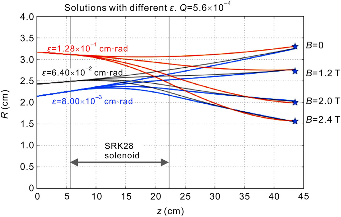
The Neutralized Drift Compression Experiment-II (NDCX-II) is an induction linac that generates intense pulses of 1.2 MeV helium ions for heating matter to extreme conditions. Here, we present recent results on optimizing beam transport. The NDCX-II beamline includes a 1-m-long drift section downstream of the last transport solenoid, which is filled with charge-neutralizing plasma that enables rapid longitudinal compression of an intense ion beam against space-charge forces. The transport section on NDCX-II consists of 28 solenoids. Finding optimal field settings for a group of solenoids requires knowledge of the envelope parameters of the beam. Imaging the beam on the scintillator gives the radius of the beam, but the envelope angle is not measured directly. We demonstrate how the parameters of the beam envelope (radius, envelop angle, and emittance) can be reconstructed from a series of images taken by varying the B-field strengths of a solenoid upstream of the scintillator. We use this technique to evaluate emittance at several points in the NDCX-II beamline and for optimizing the trajectory of the beam at the entry of the plasma-filled drift section.
P.A. Seidl, J.J. Barnard, E. Feinberg, A. Friedman, E.P. Gilson, et al., Irradiation of materials with short, intense ion pulses at NDCX-II, Laser Part. Beams 35 (2017) 373.10.1017/s0263034617000295
[2]
Q. Ji, P.A. Seidl, W.L. Waldron, J.H. Takakuwa, A. Friedman, et al., Development and testing of a pulsed helium ion source for probing materials and warm dense matter studies, Rev. Sci. Instrum. 87 (2016) 02B707.10.1063/1.4932569
[3]
E.P. Gilson, R.C. Davidson, P.C. Efthimion, I.D. Kaganovich, J.W. Kwan, et al., Ferroelectric plasma sources for NDCX-II and heavy ion drivers, Nucl. Instrum. Methods Phys. Res. A 733 (2014) 75.10.1016/j.nima.2013.05.091
[4]
I.D. Kaganovich, R.C. Davidson, M.A. Dorf, E.A. Startsev, A.B. Sefkow, et al., Physics of neutralization of intense high-energy ion beam pulses by electrons, Phys. Plasmas 17 (2010) 056703.10.1063/1.3335766
[5]
K. Poorrezaei, R.B. Fiorito, R.A. Kishek, B.L. Beaudoin, New technique to measure emittance for beams with space charge, Phys. Rev. Spec. Top. Accel. Beams 16 (2013) 082801.10.1103/physrevstab.16.082801
[6]
D. Stratakis, K. Tian, R.A. Kishek I. Haber, M. Reiser, et al., Tomographic phase-space mapping of intense particle beams using solenoids, Phys. Plasmas 14 (2007) 120703.10.1063/1.2823037
[7]
J. Kennedy, Particle swarm optimization, In: Encyclopedia of machine learning, Springer, 2011, p. 760.
[8]
S.M. Lund, T. Kikuchi, R.C. Davidson, Generation of initial kinetic distributions for simulation of long-pulse charged particle beams with high space-charge intensity, Phys. Rev. Spec. Top. Accel. Beams 12 (2009) 114801.10.1103/physrevstab.12.114801
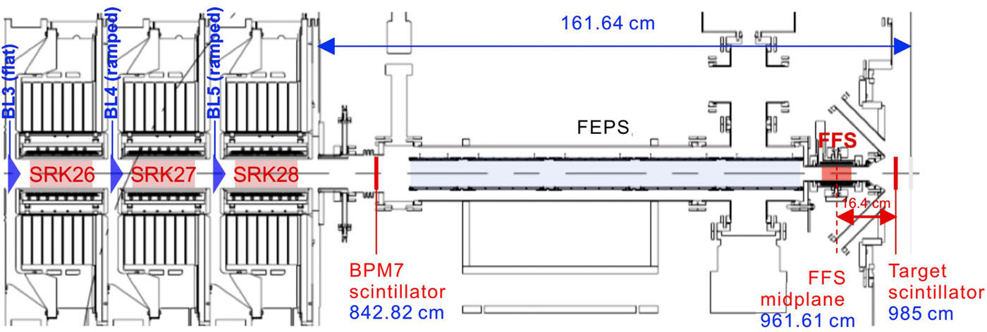
Figure Fig. 1. NDCX-II beamline. The accelerator is 10-m-long from source to target. The He+ ion beam is extracted from a multicusp plasma ion source and transported through a 28-solenoid lattice towards the Ferroelectric Plasma Source (FEPS). Inside the FEPS, a volume plasma is generated that neutralizes the space-charge of the beam and enables longitudinal and transverse compression of the ion pulse. The locations where the scintillator measurements of the beam spot size were taken are indicated in this Figure.
Figure Fig. 2. Example plots of a set of envelope trajectories through the last transport solenoid upstream of the FEPS. Different values of emittance (in units of cm·rad) can reproduce experimental data.
Figure Fig. 3. (a) Schematic illustration of the self-similar transformation j(r)→j(r⋅M)/M2. (b) Beam profiles j(r) after the transformation j(r)→j(r⋅M)/M2 is applied, where M is a scalar magnification factor. The plot shows that the shape of the transformed j(r) profiles is approximately the same, i.e. the j(r) profiles are self-similar. Different colors correspond to different focusing strengths of the solenoid lens upstream of the scintillator, from B = 0 T (#2, purple) to B = 2.4 T (#13, blue). (c) Beam radius vs. B-field strength in the upstream solenoid. The radius R(B) is determined from the self-similarity factor M as R(B)=Rs⋅M(B), where Rs is the radius of the profile chosen as the “standard” profile with M=1.
Figure Fig. 4. Geometry of the measurement to infer the beam envelope parameters at the entry top of the last transport solenoid immediately upstream of the FEPS.
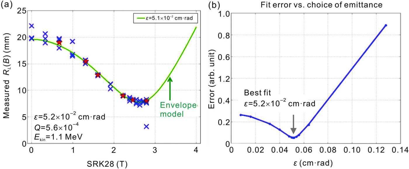
Figure Fig. 5. (a) Measured RL(B) at increased fields in solenoids #26 and #27. (b) Fit error vs. choice of emittance, showing a minimum at ε = 5.2 × 10⁻² cm⋅rad.
Figure Fig. 6. (a) Setup of the source emittance measurement. The scintillator was placed 134 cm downstream of the ion source. Solenoid #1 was set at 0.8 T to direct the ion current from the source into the accelerator. The field in solenoid #2 was varied for the scan, while solenoid #3 was turned off to give the beam some drift distance; (b) Measured beam radius vs. the B-field in solenoid #2.


 DownLoad: